Creating an Inbound Integration Pipeline
The basic workflow to create an inbound integration pipeline:
Create an integration pipeline.
Create a pipeline interface.
Create a message queue.
Execute the pipeline.
View the pipeline execution history.
This page provides the instructions for the first step in this workflow. See the subsequent sections for information on each step. This example covers inbound integration from a JSON file. Users can also use the pipeline to integrate data from CSV and XML files.
Prerequisites for following along with the example shown in each section of this documentation:
Identify the Value Chain ID (VC ID) for your dataset.
Identify the Enterprise and Organization you would like to use. You can either create a HUB4 Enterprise and HUB4 Organization to mimic the sample data and code provided, or use your own and change references to HUB4 within our sample data and code.
Complete the following steps to create a new integration pipeline:
Log in to the ONE system.
Click Menu/Favs > Tools > Integration > NEO Plasma Pipelines.
The NEO Plasma Pipelines screen appears.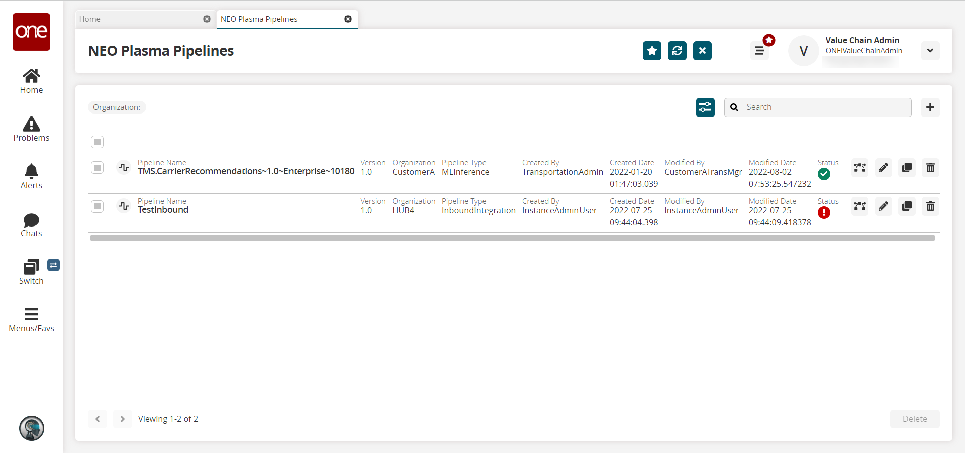
Click the + (plus) icon in the top right corner.
The Create NEO Plasma Pipeline popup window appears.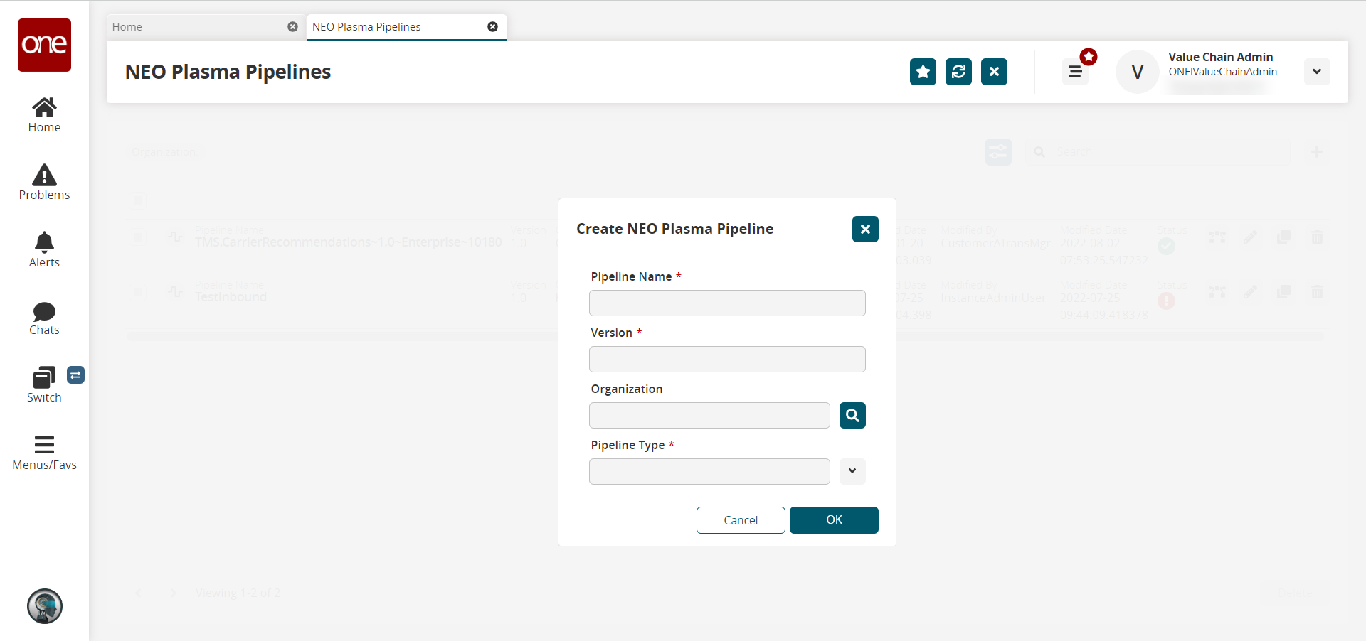
Fill out the following fields. Fields with an asterisk ( * ) are required.
Field
Description
Pipeline Name *
Enter a name for the new pipeline.
Version *
Enter a version number for the new pipeline.
Organization
Use the picker tool to select the organization.
Pipeline Type *
Select the pipeline type from the dropdown menu. The options are Inbound Integration and Outbound Integration. For this example, select Inbound Integration.
Click OK.
The new pipeline appears on the NEO Plasma Pipelines screen.Click the pipeline icon (highlighted below) to view the new pipeline.
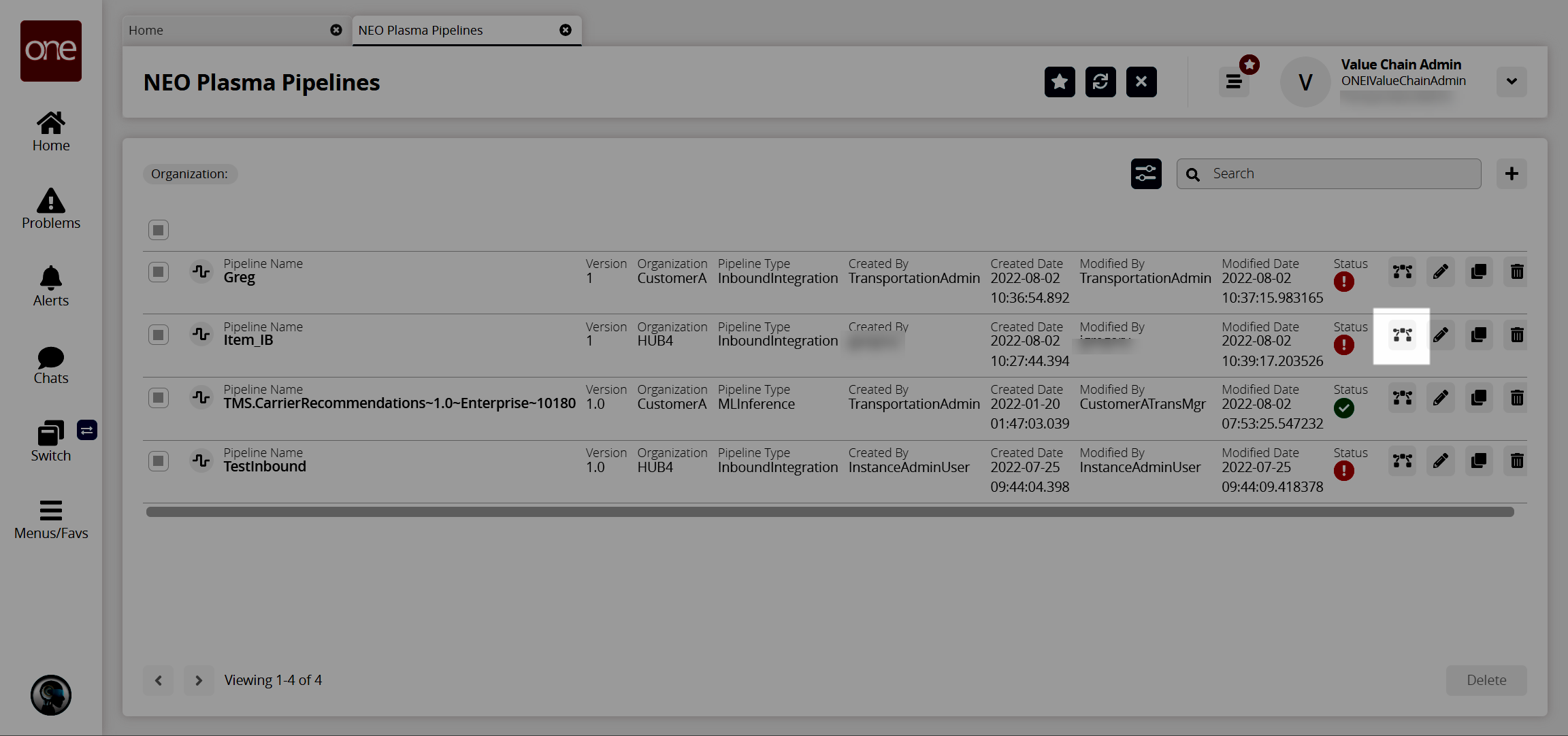
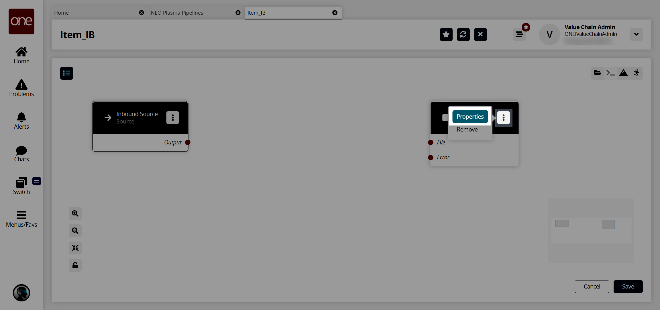
The new pipeline appears with Inbound Source and Inbound Sink nodes displayed.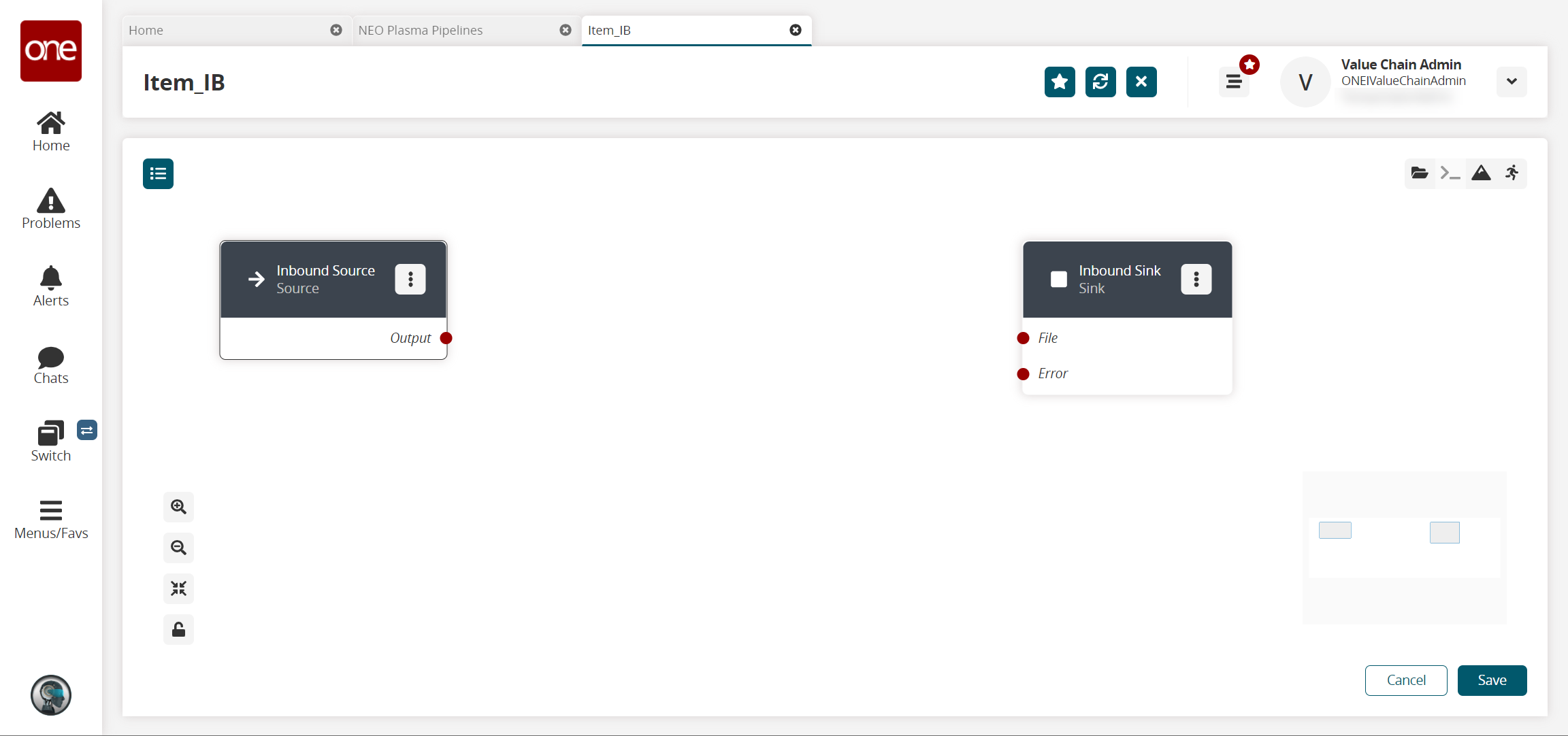
On the Inbound Sink node, click the icon with three vertical dots and click Properties.
The Node Properties popup window displays.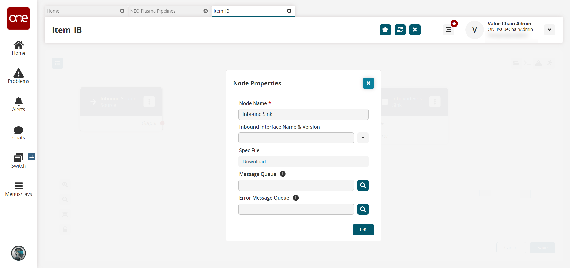
Fill out the following fields. Fields with an asterisk ( * ) are required.
Field
Description
Node Name *
This field auto-populates for the Inbound Sink node.
Inbound Interface Name & Version
Select the interface from the dropdown menu.
Spec File
Click the Download link to download a spec file. A spec file is a CSV file with sample data.
Message Queue
Use the picker tool to select a message queue.
Error Message Queue
Use the picker tool to select an error message queue.
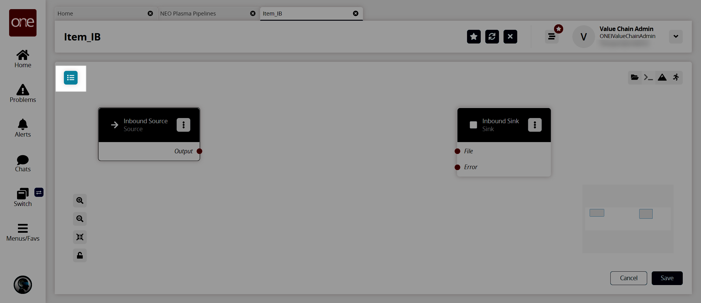
Click OK.
The pipeline screen appears.Click the Node List icon in the top left corner.
The Node List slideout appears.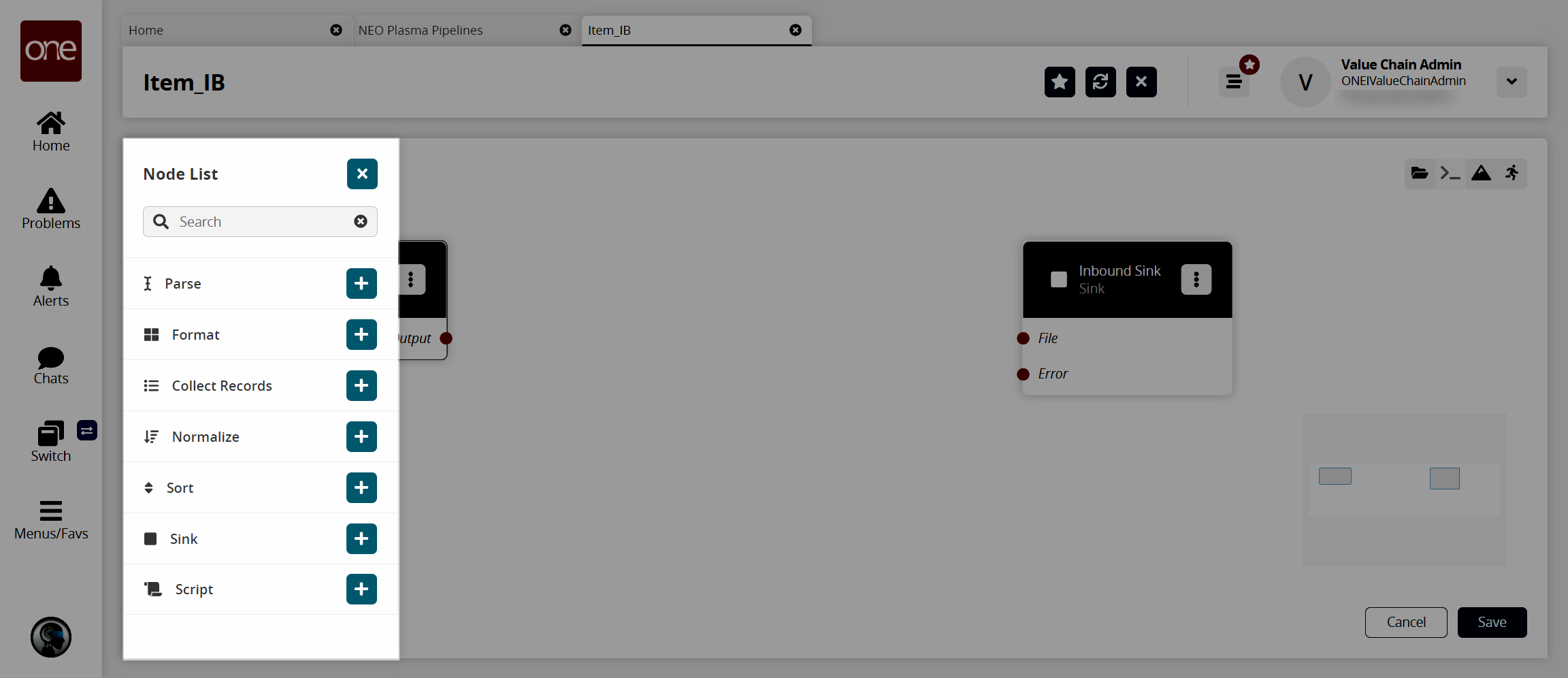
Click the + (plus) icon for the type of node you want to add. For this example, we selected a parse node. The parse node parses the inbound file data into records.
The parse node appears in the pipeline.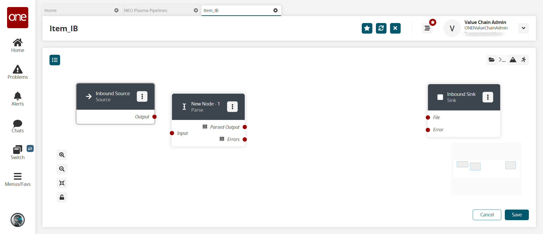
On the new node, click the icon with three vertical dots and click Properties.
The Node Properties popup window appears.Download this file. You will upload this sample file in the next step. Alternatively, use the data in the "Sample JSON File" section of this guide to create your own JSON file to upload in the next step.
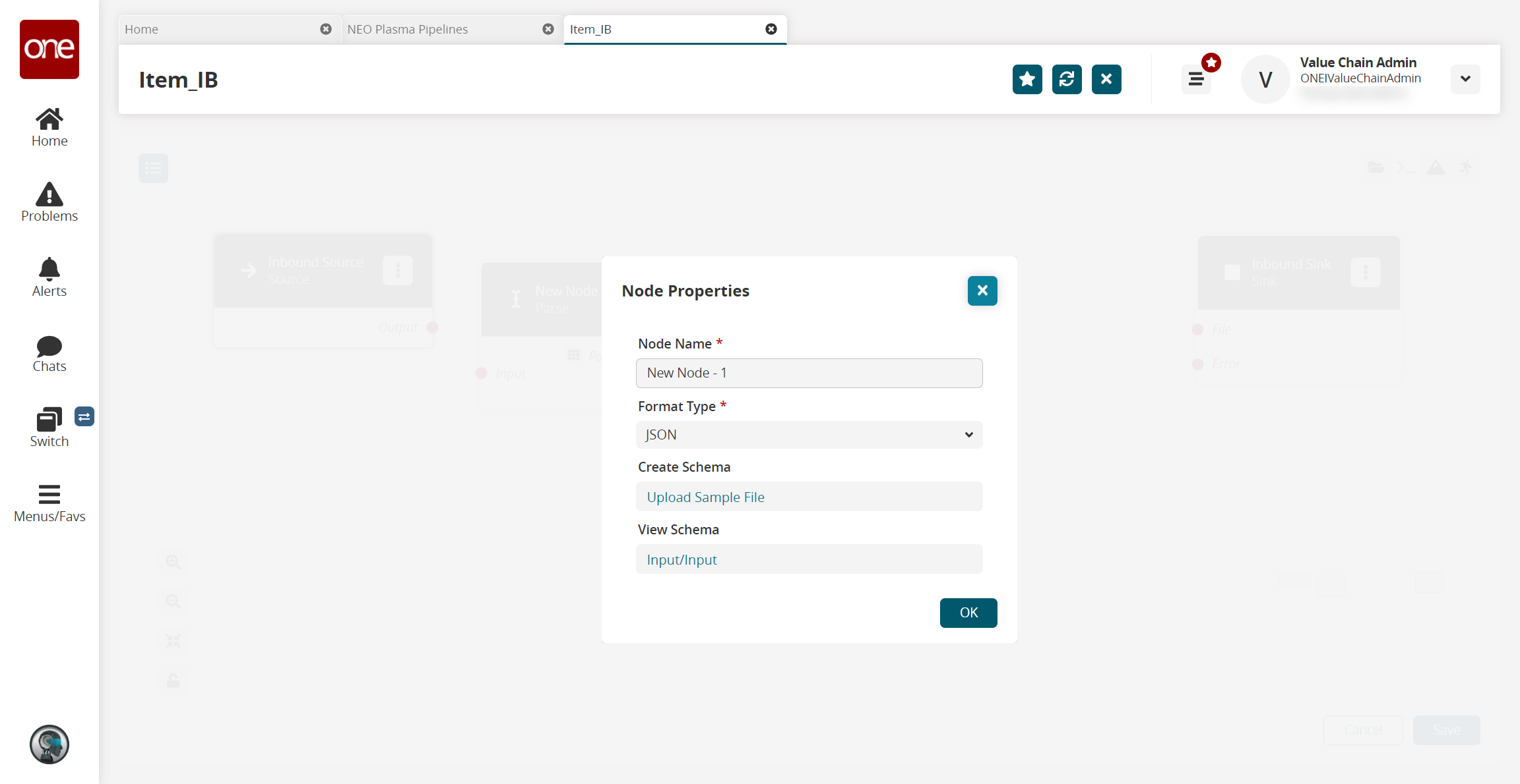
Fill out the following fields. Fields with an asterisk ( * ) are required.
Field
Description
Node Name *
Enter a name for the node.
Format Type *
Select a format type for the inbound file from the dropdown list. Options are JSON, CSV, and XML. The remaining fields vary according to the format chosen. For this example, we selected JSON.
Create Schema
a. Click the Upload Sample File link.
The Create Schema popup appears.
b. Complete the following fields. Fields with an asterisk are required.Field
Description
Namespace *
Enter a unique category to organize schema name fields.
Schema *
Enter a unique name with which to associate the dataset.
Sample File *
Click the upload icon to upload a sample file for the parse node. For this example, you can use the same JSON file downloaded in the previous step, or create a JSON file using the data in the "Sample JSON file" section.
JSON Root *
Select the JSON root you want the parser to use.
c. Click OK.
The Node Properties updates.View Schema
This field auto-populates with a link once the sample file is uploaded in the Create Schema field. Click the link to view or edit the record schemas.
Click OK.
The pipeline screen updates.On the Inbound Source node, click the red dot next to Output and drag the cursor to connect to the Input on the Parse node.
The connection turns green. The parse node can now parse the data from the inbound source into records.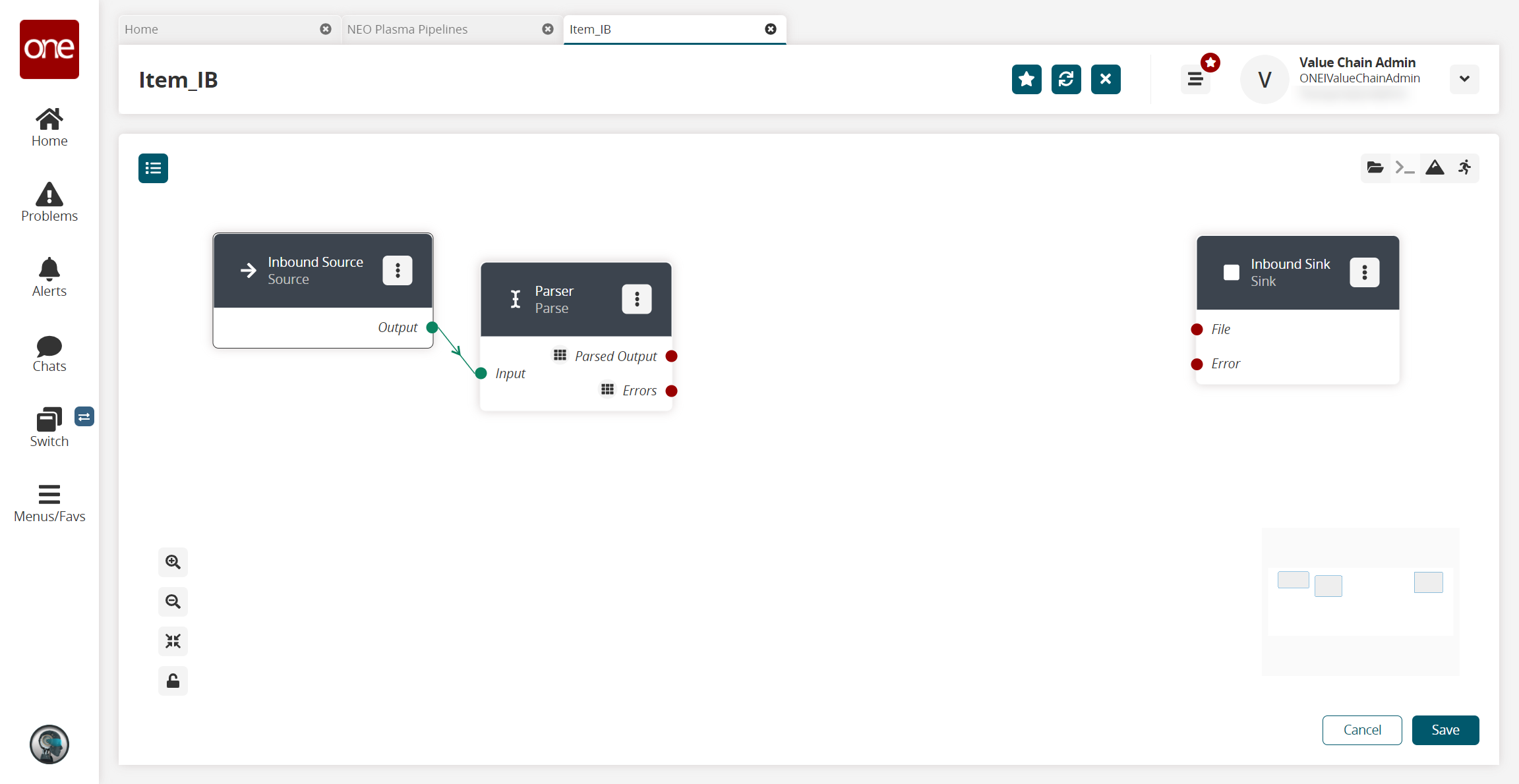
Click the node list icon in the top left corner again.
The Node List slideout reappears.Click the + (plus) icon next to Script.
A script node is added to the pipeline.On the new script node, click the icon with three vertical dots and click Properties.
The Node Properties popup window appears.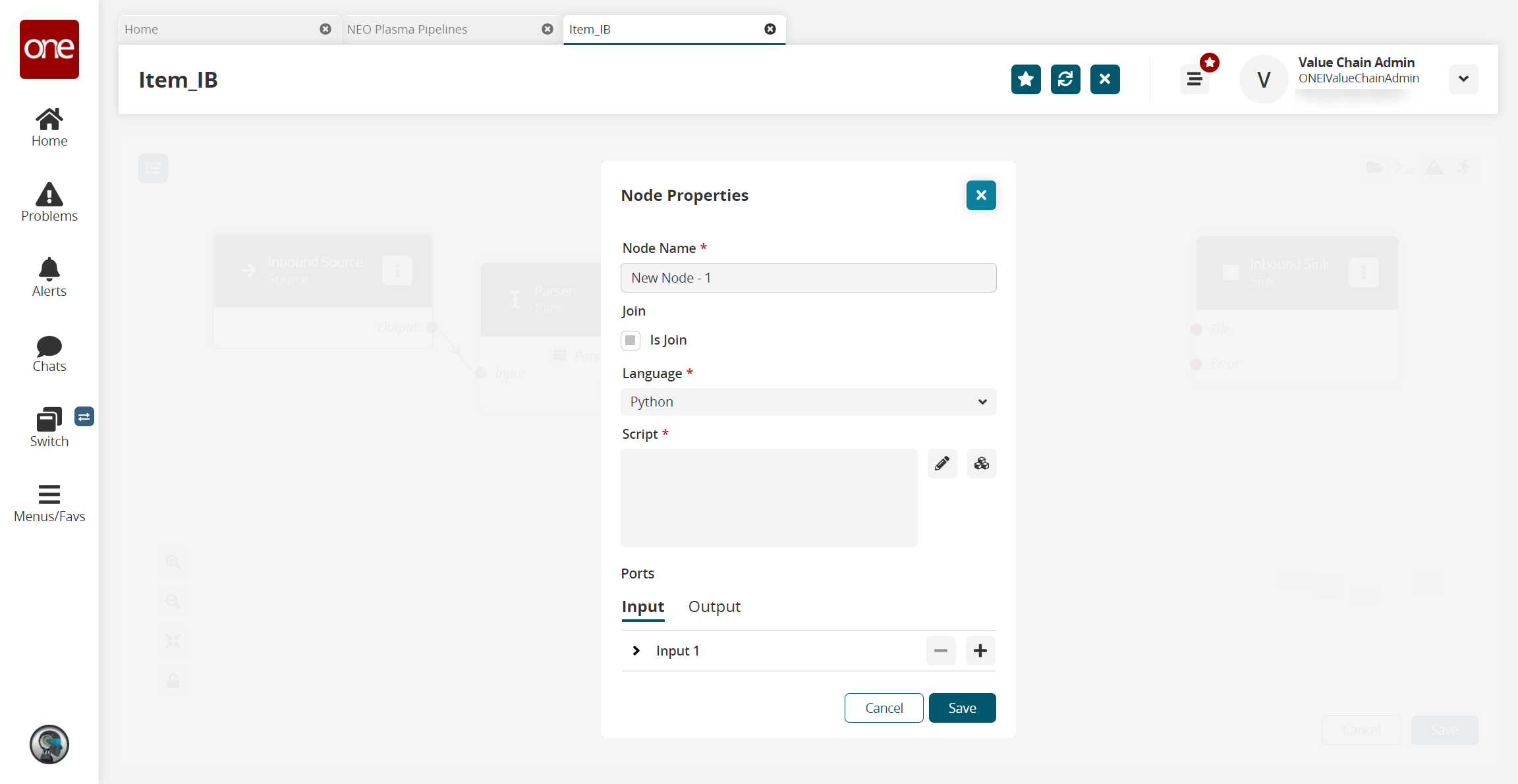
On the Input tab in the Ports section, click the arrow to display the port fields.
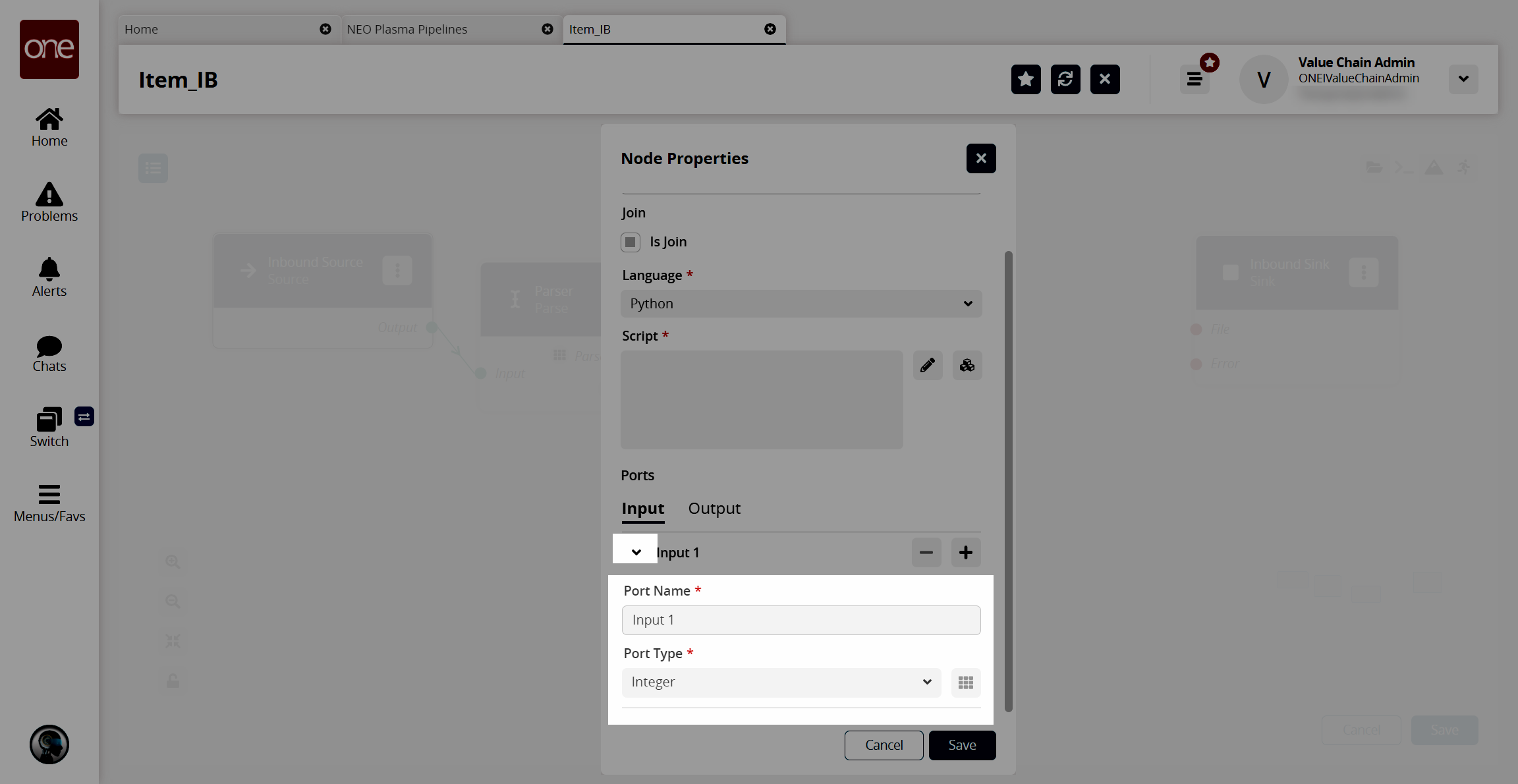
In the Port Type * field, select Stream of Record from the dropdown list.
The icon beside the dropdown list becomes active.Click the icon beside the Port Type * dropdown list.
The Record Schemas popup window displays.Click the arrow beside Input.
The list of schemas displays.Select the schema.
The schema displays in the pane to the right, and the Activate button becomes active.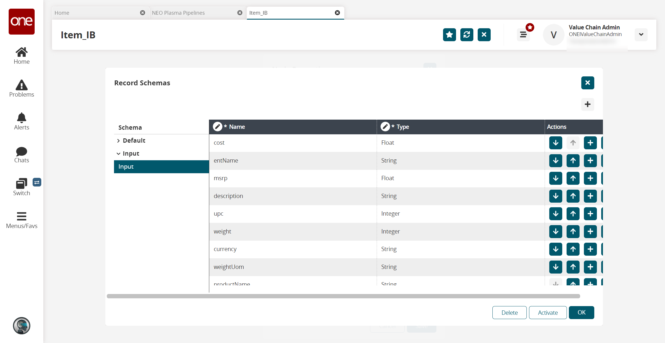
Click the Activate button.
Click OK.
The Node Properties popup window appears again.In the Ports section, click the Output tab.
Click the arrow to the left of the output to display the Port Name * and Port Type * fields.
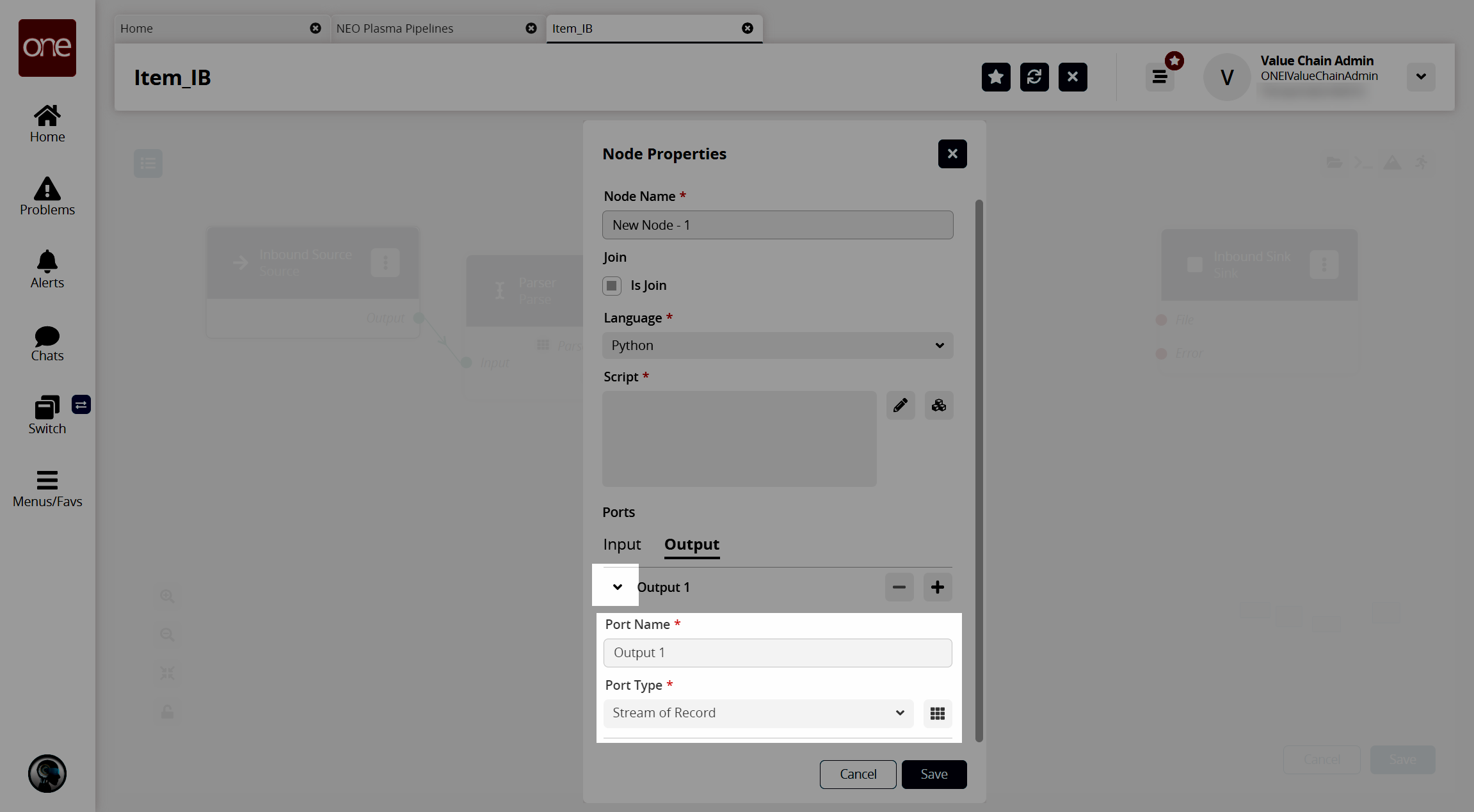
In the Port Type * field, select Stream of Record from the dropdown list.
Click the icon to the right of the Port Type * dropdown list.
The Record Schemas popup window displays.In the Schema pane on the left, click the arrow beside Default.
The Output record schemas display in the pane.Click the interface selected on the Inbound Sink node previously.
The schema displays in the pain to the right, and the Activate button becomes active.Click the Activate button.
Click OK.
The Node Properties popup window reappears.In the Script * field on the Node Properties popup window, click the pencil icon.
The Edit Script popup window appears.Enter the script code for the node. A sample script code is shown below.
def executeNode(inputs):iterable_inputs = {}outputs = {}# Input portsiterable_inputs["Input 1"] = inputs["Input 1"]# Type = stream.record# cost, msrp, description, upc, weight, currency, weightUom, productName# Add node logic hereforrecord in iterable_inputs["Input 1"]:yield {"Output 1": {"ItemName": record["productName"],"Description": record["description"],"ManagingEntName": record["entName"],"ManufacturerPrice": record["msrp"],"Price": record["msrp"],"Currency": record["currency"],"CaseUPC": record["upc"],"PackageUPC": record["upc"],"Weight": record["weight"],"WeightUOM": record["weightUom"],"Active": True}}# Activate and set outputs (omit a port to prevent execution of nodes that depend on that port)# Type = stream.record# ManagingEntName, ManagingOrgName, ItemName, PartnerName, Description, CaseUPC, PackageUPC, UniversalItemName,# GlobalTradeItemNumber, StandardCost, PurchaseCost, TotalLandedCost, Price, ManufacturerPrice, Currency, Length,# Width, Height, LinearUOM, Weight, WeightUOM, UnitsPerCase, CasesPerPallet, UnitsPerPallet, CaseLength, CaseWidth,# CaseHeight, CaseLinearUOM, CaseWeight, CaseWeightUOM, PalletLength, PalletWidth, PalletHeight, PalletLinearUOM,# PalletWeight, PalletWeightUOM, UnitsPerLayer, LayersPerPallet, ItemType, ItemClass, ItemCategory, CommodityCode,# Style, Color, Size, StockingUOM, OrderingUOM, OrderingToStockingConversionFactor, ManufacturerPartner,# ManufacturerEnterpriseName, ManufacturingItemName, ActivationDate, DeactivationDate, Active, InitialDuration,# InitialDurationUOM, GrowthDuration, GrowthDurationUOM, MaturityDuration, MaturityDurationUOM, DeadlineDuration,# DeadlineDurationUOM, ShelfLife, ShelfLifeUOM, LikeItemName, IsLotControlled, IsSerialControlled, IsNeverOutItem,# Stackable, PlannerCode, ReplenishmentType, DrawingNumber, Notes, ModelSupplyChain, Hazardous,# HazmatNumberHazmatNumber, HazmatNumberCategory, ProperShippingNameName, HazardClassName, HazmatContactName,# HazmatContactPhone, HazmatPackagingGroup, FreightClass, HTSCode, OrderMgmtOrgEnterpriseName, OrderMgmtOrgName,# CycleCountingFrequency, Spaces, ExtManufacturerItemName, ReversePartnerEntName, ReversePartnerOrgNamereturnoutputsClick Save.
The Node Properties popup window appears.Click Save.
The pipeline screen reappears.On the Parse node, click the red dot next to Parsed Output and drag the cursor to connect to Input 1 on the script node.
The connection turns green. The stream of records from the parser has now been converted to the correct format.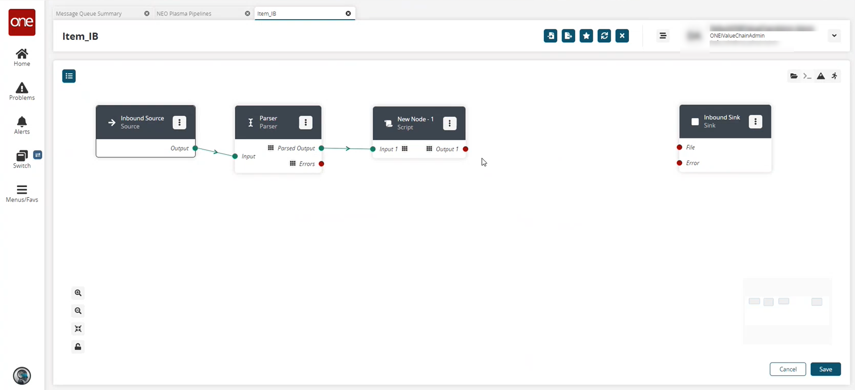
Click the node list icon in the top left corner again.
The Node List slideout reappears.Click the + (plus) icon next to Format.
A format node is added to the pipeline.On the new Format node, click the icon with three vertical dots and click Properties.
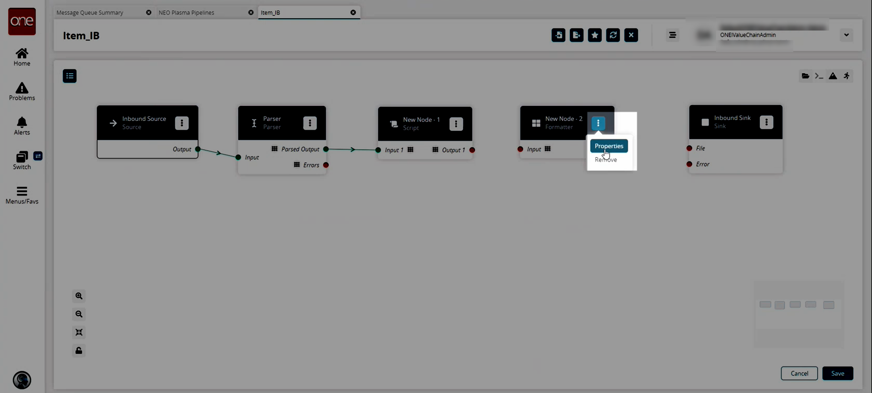
The Node Properties popup window appears.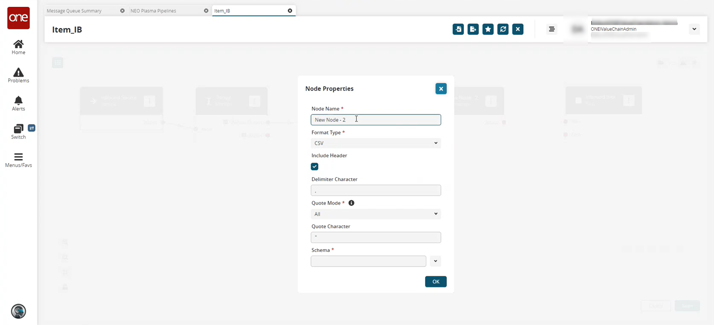
Fill out the following fields. Fields with an asterisk ( * ) are required.
Field
Description
Node Name *
Enter a name for the node.
Format Type *
Select the desired format type from the dropdown list. For this example, we used CSV. Note that the remaining fields vary based on the format type selected.
Include Header
Click the checkbox to include the header when formatting the data.
Delimiter Character
Enter a delimiter character or leave the default
Quote Mode *
Select a quote mode from the dropdown list.
Quote Character
Enter a quote character or level the default
Schema *
Select the output schema from the dropdown list.
Click OK.
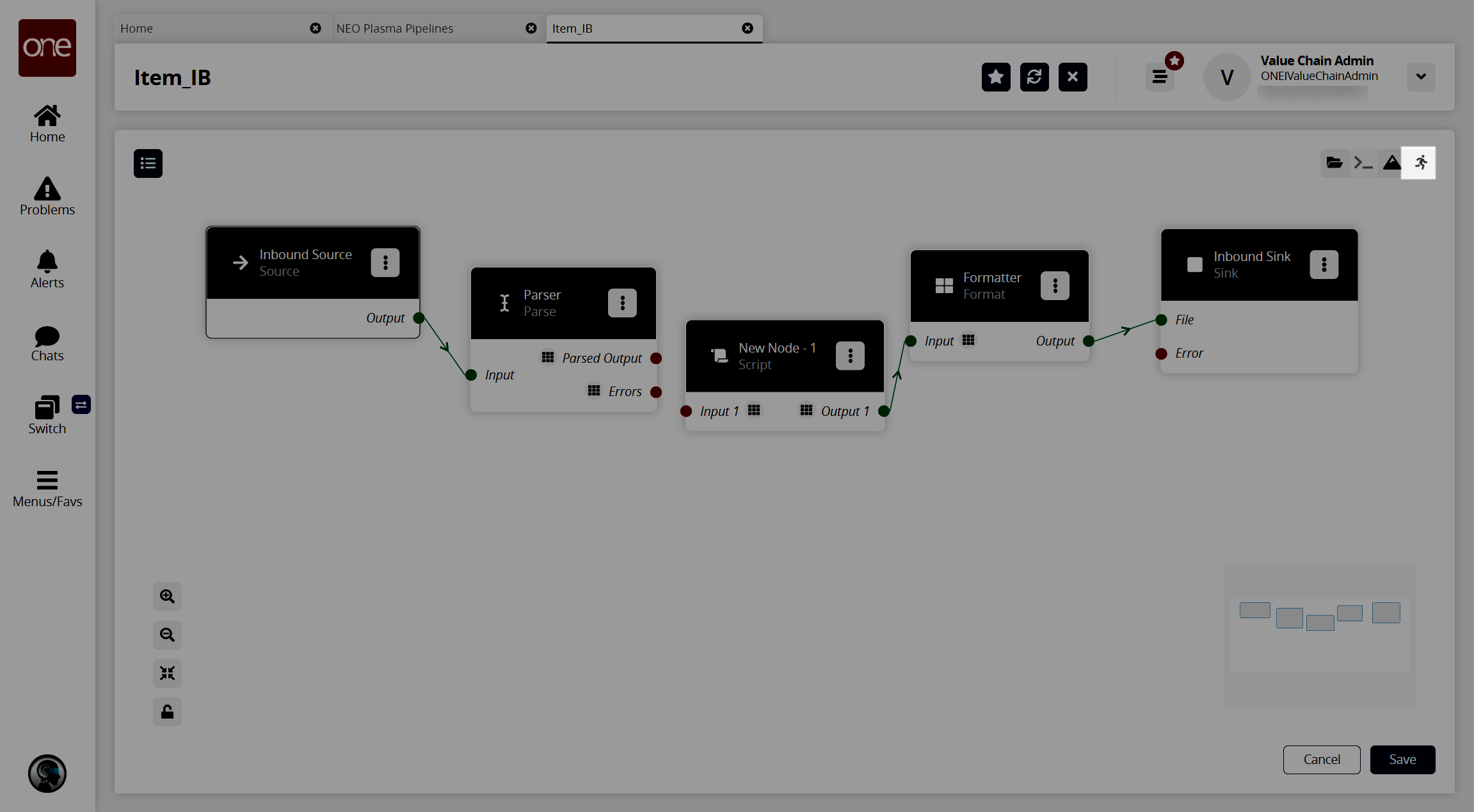
The pipeline screen reappears.On the Format node, click the red dot next to Output and drag the cursor to connect to File on the Inbound Sink node.
Repeat this process to add additional nodes as desired. The following node types are available:
Parse
Format
Collect Records
Normalize
Sort
Script
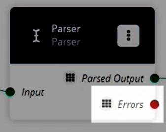
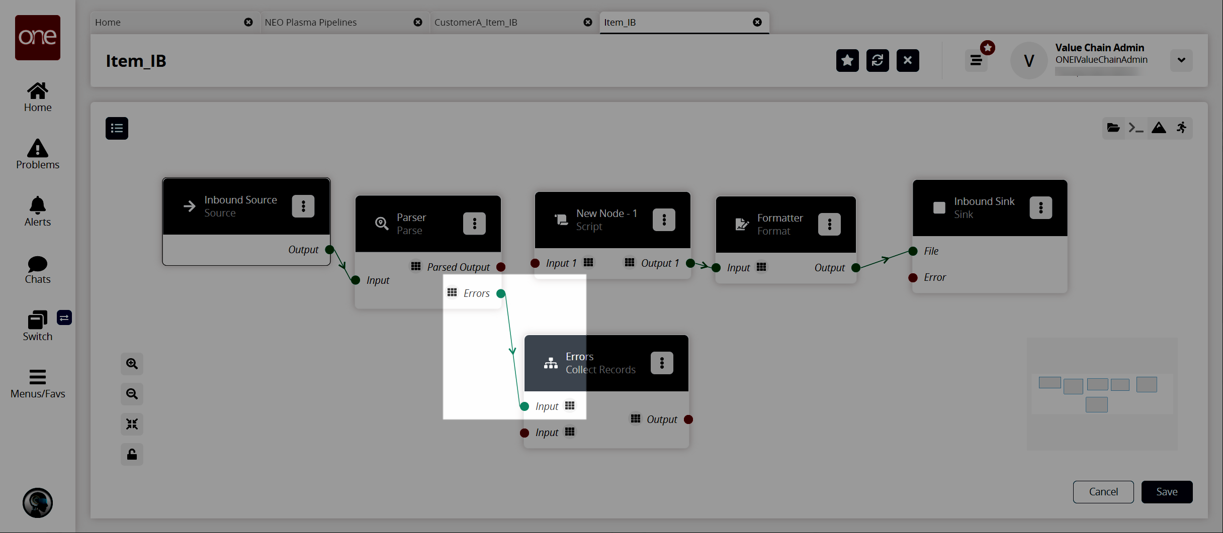
If a pipeline node has an Errors output label, as shown in the image below, error handling should be set up.
To set up error handling, click the node list icon in the top left corner again.
The Node List slideout reappears.Click the + (plus) icon next to Collect Records.
A Collect Records node is added to the pipeline.On the new Collect Records node, click the icon with three vertical dots and click Properties.
The Node Properties popup window appears.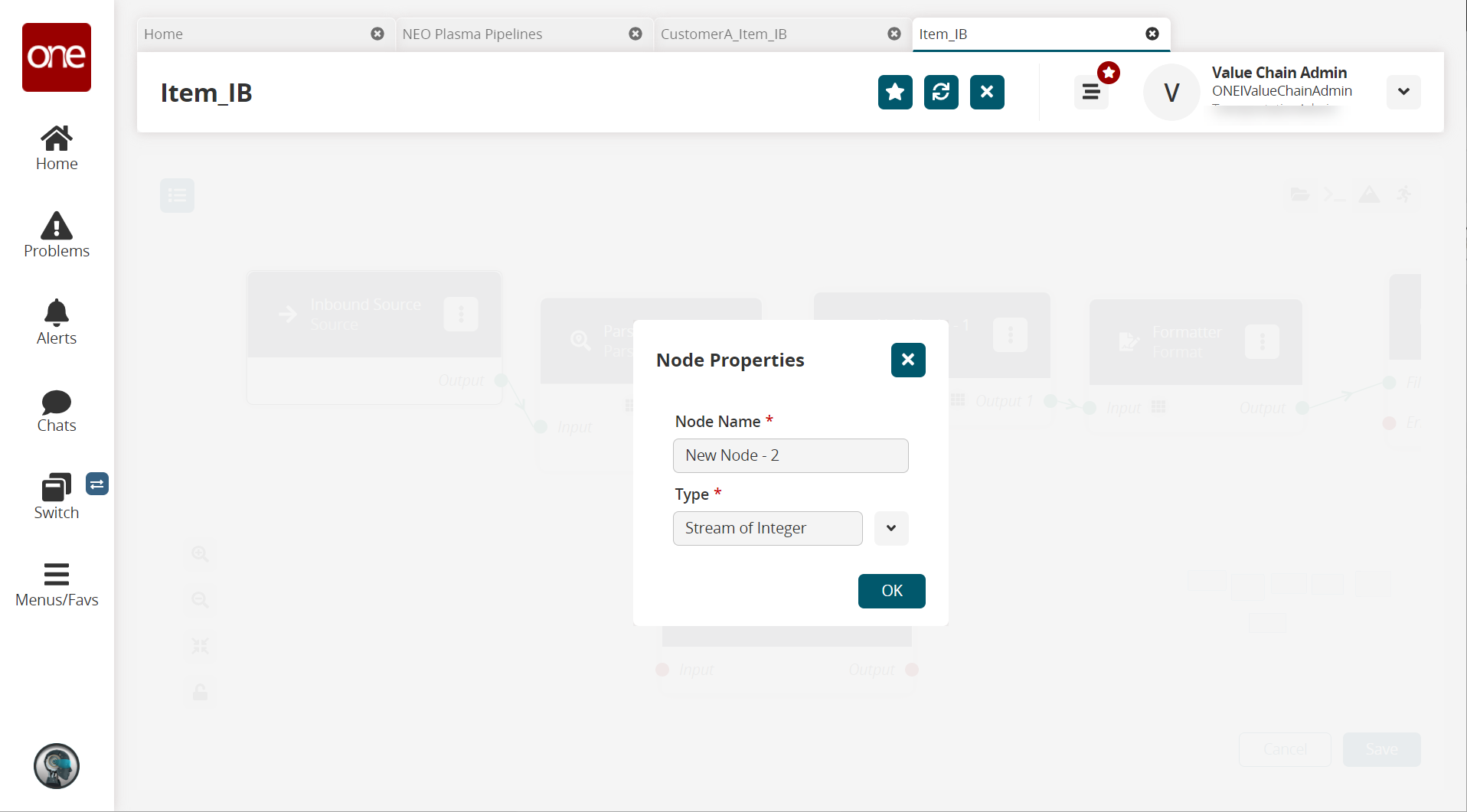
In the Node Name * field, enter a name for the collector node. This field is required.
In the Type * field, select Stream of Records from the dropdown list.
The Schema field appears.Select Default/Errors from the dropdown list.
Click OK.
The pipeline details screen reappears.Connect the Parse node (or the node with the Errors output) with the error collector node.
Click the node list icon in the top left corner again.
The Node List slideout reappears.Click the + (plus) icon next to Format.
A format node is added to the pipeline.On the new Format node, click the icon with three vertical dots and click Properties.
The Node Properties popup window appears.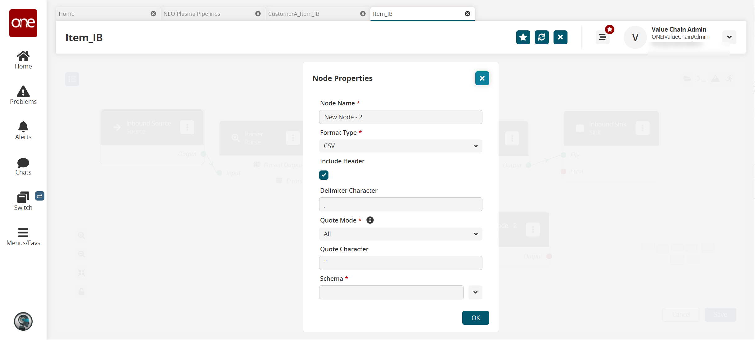
Fill out the following fields. Fields with an asterisk ( * ) are required.
Field
Description
Node Name *
Enter a name for the node.
Format Type *
Select CSV from the dropdown list.
Include Header
Click the checkbox to include the header when formatting the data.
Delimiter Character
Enter a delimiter character or leave the default
Quote Mode *
Select Minimal from the dropdown list.
Quote Character
Enter a quote character or level the default
Schema*
Select the Default/Error output schema from the dropdown list.
Click OK.
The pipeline details screen returns.Connect the error collector output to the format node input, and connect the format node output to the Inbound Sink node as shown below.
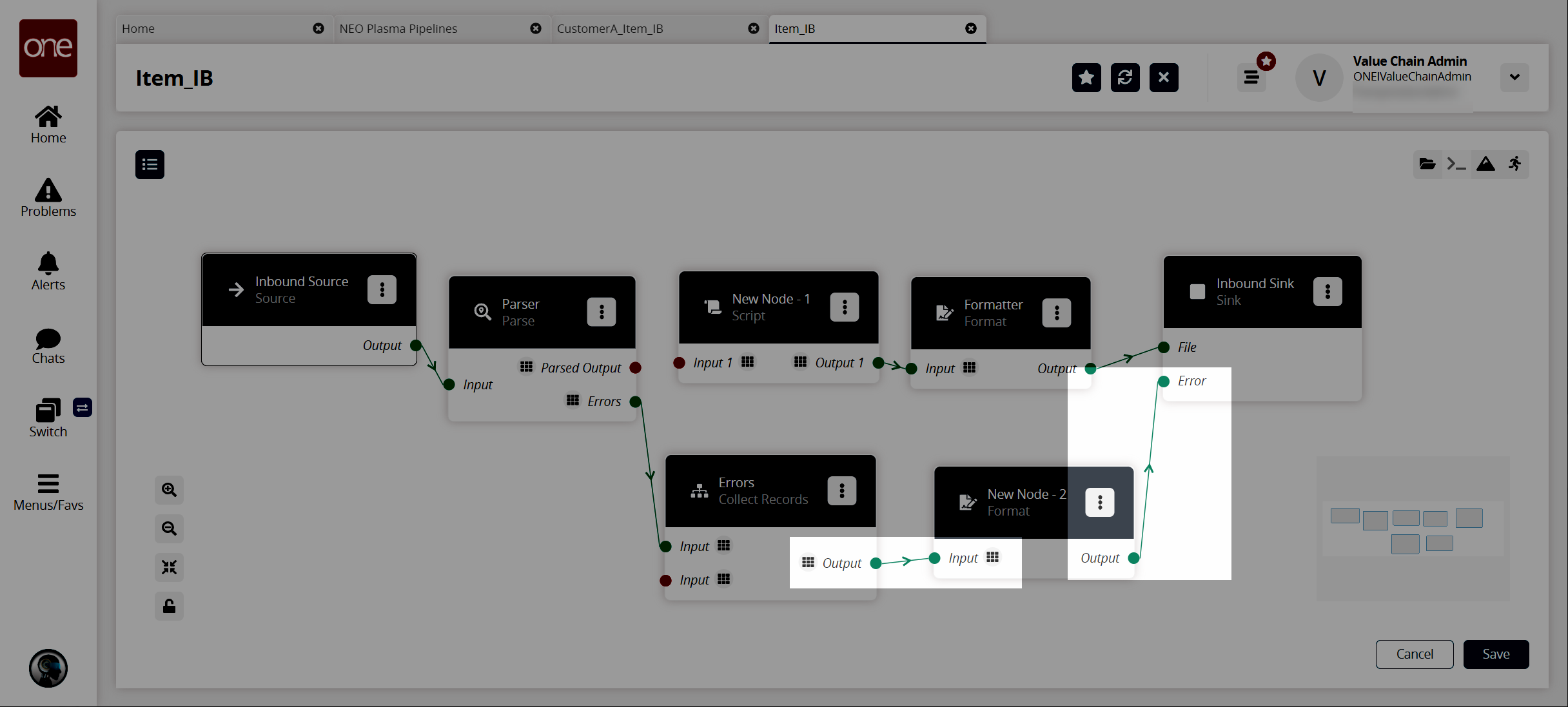
Click the Save button to save the pipeline.
Click the Run Test icon in the top right corner to test the pipeline.
The Test Run Pipeline slideout appears.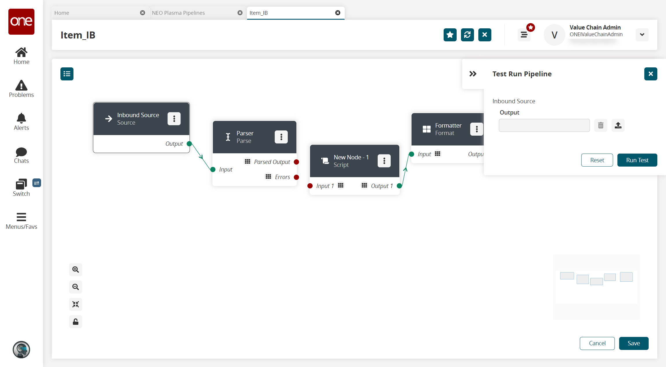
Click the upload icon to upload the inbound source file.
Click the Run Test button.
The Node Logs section appears at the bottom of the screen with the successful nodes turning green in the Execution Sequence column.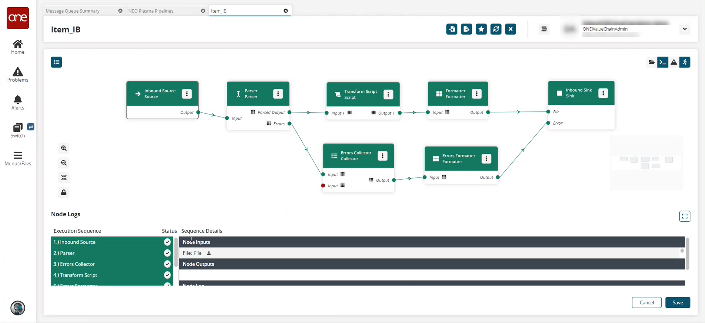
In the Sequence Details column of the Node Logs section, click the File download link under node inputs to download the file created in the Inbound Sink node.
Go to your download location to view the output and verify that it is correct.
If the test run is correct, the next step is to create a pipeline interface. See the "Creating a Pipeline Interface" section for instructions.